Configure Cameras
Set the view and projection conventions for 3D panels.
This page configures the initial viewpoint and projection. Choose interaction separately in Use 3D controllers, and use coordinate systems to decide how visual positions map into a panel.
At a glance
- Status: Supported perspective and orthographic panel camera descriptors.
- Languages: C-first; Python exposes the exact generated descriptor call form.
- Prerequisites: A 3D panel and known data center, extent, axis convention, and units.
- Result: The first frame uses an explicit eye, target, up direction, projection, and clipping range.
Task workflow
Use panel domains and panzoom for 2D data. For 3D data, configure a panel camera or use a 3D controller that updates camera/view state. Keep camera state separate from mesh data so navigation does not rewrite geometry.
Camera setup answers different questions than controller selection:
| Question | Page |
|---|---|
| Which interaction model should the user get: arcball, turntable, or fly? | Use 3D controllers |
| Where is the eye, what is it looking at, what is up, and how is depth projected? | This page |
A camera descriptor defines the initial view and projection:
| Field | Meaning |
|---|---|
view.eye |
Camera position in scene coordinates. |
view.target |
Point the camera looks at. |
view.up |
Direction treated as vertical for the view. Use a consistent world-up convention across the scene. |
projection.type |
Perspective or orthographic projection. |
projection.fov_y |
Vertical field of view for perspective cameras, in radians. |
projection.ortho_height |
Visible height for orthographic cameras. |
projection.near_clip, projection.far_clip |
Clipping planes. Choose values that enclose the data without making the depth range needlessly large. |
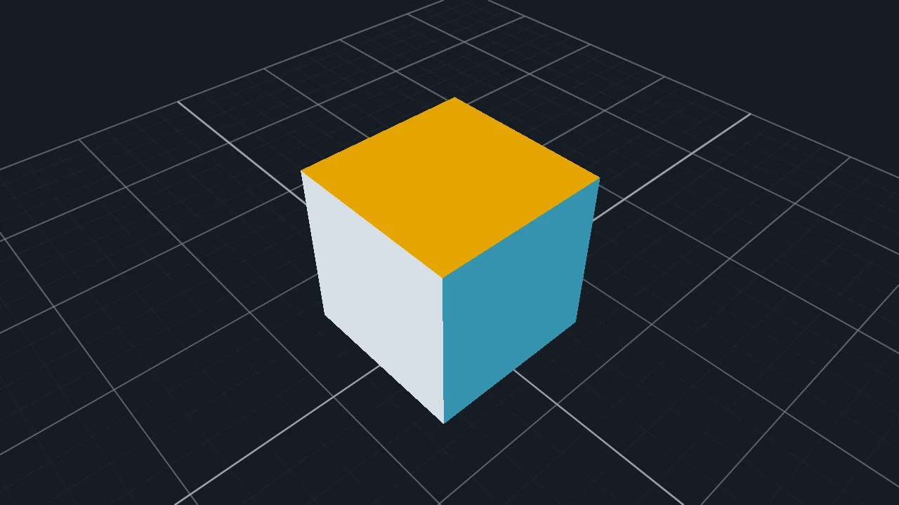
The camera first establishes a view convention, then projects and clips the visible geometry. A controller may update that retained camera state later without modifying the geometry itself.
Minimal call sequence
This is a C setup excerpt. Check that dvz_panel_set_camera_desc() succeeds and attach the intended
3D controller/live input path separately.
DvzCameraDesc camera = dvz_camera_desc();
camera.view.eye[0] = 0.0f;
camera.view.eye[1] = 1.5f;
camera.view.eye[2] = 4.0f;
camera.view.target[0] = 0.0f;
camera.view.target[1] = 0.0f;
camera.view.target[2] = 0.0f;
camera.view.up[0] = 0.0f;
camera.view.up[1] = 1.0f;
camera.view.up[2] = 0.0f;
camera.projection.near_clip = 0.01f;
camera.projection.far_clip = 100.0f;

dvz_panel_set_camera_desc(panel, &camera);
Attach a controller after setting the camera when the example needs interactive navigation. Turntable and fly descriptors commonly reuse the same target, eye, or up convention. Arcball is primarily object-inspection state, but it still depends on a clear view convention for predictable drag axes and lighting.
The result is a panel whose first rendered frame uses this camera.
The descriptor is copied by the panel setter. The local camera variable may go out of scope after
the call; later controller changes update retained panel/camera state, not this stack copy.
Important details
Camera conventions affect depth, lighting, picking, labels, and orientation UI. Confirm the scene's axis convention before adding a grid, orientation gizmo, scientific labels, or a controller with a world-up direction.
Center or normalize imported geometry before choosing camera distances. If the data is very large or very small, adjust controller speeds and clipping planes to match the same scale.
Use perspective projection for most spatial inspection. Use orthographic projection when apparent size should not depend on distance, for example CAD-like inspection, aligned volumes, or physical scale comparisons.
Common mistakes
- Using visual transforms as camera transforms.
- Combining 2D domain navigation and 3D camera navigation on the same panel.
- Choosing
projection.near_clipandprojection.far_clipvalues that clip the data or waste depth precision. - Forgetting to center or scale imported geometry before attaching a 3D controller.
- Letting the controller imply an axis convention that disagrees with labels, lighting, or the orientation gizmo.
Next steps
Complete and related examples
- Canonical complete example: Arcball Controller - Source:
examples/c/features/controller_arcball.c - Orientation Gizmo - Source:
examples/c/features/orientation_gizmo.c